")
Key Features
- ATmega32U4 with Arduino Leonardo bootloader on the board
- MCP2515 CAN Bus controller and MCP2551 CAN Bus transceiver
- OBD-II and CAN standard pinout selectable at the sub-D connector
- Compatible with Arduino IDE
Description
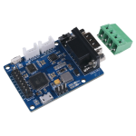
CANBed – Arduino CAN-BUS Development Kit embeds an ATmega32U4 chip, which means you don’t need to add other jump wires to another Arduino Board, it is an Arduino board itself plus MCP2515 CAN Bus controller and MCP2551 CAN Bus transceiver!
CAN-BUS is a common protocol and widely used in industry due to its long travel distance, medium communication speed, and high reliability. Now you can realize a CAN-BUS project through this tiny little development board.
Because of the ATmega32U4 onboard chip, this board has rich resources in pins. As a matter of fact, there are 18 pins based on core chip set up on the board, which include digital pins, analog pins, UART, and I2C interface. Besides, this CANBed adopts MCP2515 CAN Bus controller with SPI interface and MCP2551 to achieve the CAN-Bus capability. There are also two kinds of CAN Bus interfaces for various demands which are sub-D9 connector and terminal block interface. They would fit all your needs in the connecting method.
This CAN-Bus development board is perfectly compatible with Arduino IDE. With the help of the Arduino CAN-Bus library, you will save plenty of time for your CAN project.
Specification
| Parameter | Value |
|---|---|
| MCU | ATmega32U4(with Arduino Leonardo bootloader) |
| Clock Speed | 16MHz |
| Flash Memory | 32KB |
| SRAM | 2.5KB |
| EEPROM | 1KB |
| Operate Voltage(CAN-BUS) | 9-28V |
| Operate Voltage (MicoUSB) | 5V |
| Input Interface | sub-D |
Hardware Overview
1.9×2 IO Pin OUT:
The IO of Atmega32U4 is listed out here
2.ATmega32U4:
The master of the entire module mainly used to store data on the TF card or transfer data to the computer through the type C cable. In addition, since it’s Arduino compatible, you can use it to implement some simple controls, such as triggering a buzzer alarm when the speed exceeds a certain value.
A: Reset Button:
Reset the on-board Atmega chip.
3.Micro USB connector for programming
4. ICSP Header for uploading bootloader
5.CAN RX/TX Indicator
6.sub-D connector or Terminal for CAN Bus
D-Sub CANbus PinOut
| pin# | Signal names | Signal Description |
|---|---|---|
| 1 | Reserved | Upgrade Path |
| 2 | CAN_L | Dominant Low |
| 3 | CAN_GND | Ground |
| 4 | Reserved | Upgrade Path |
| 5 | CAN_SHLD | Shield, Optional |
| 6 | GND | Ground, Optional |
| 7 | CAN_H | Dominant High |
| 8 | Reserved | Upgrade Path |
| 9 | CAN_V+ | Power, Optional |
7.Switch for the 120Ω terminal resistor for CAN Bus
If you use this slaver at the end of the CAN bus, you need to solder a 120Ω resister between the two pad, if not just leave them alone.
8.Grove connector for UART
9.Grove connector for I2C
Part List
- CANBed PCBA
-
sub-D connector
-
4PIN Terminal
-
4PIN 2.0 Connector x 2
-
9×2 2.54 Header x 1
-
3×2 2.54 Header x 1
CANBed – Arduino CAN-BUS Development Kit (ATmega32U4 with MCP2515 and MCP2551)
$36.00
CANBed – Arduino CAN-BUS Development Kit carries an ATmega32U4 chip and MCP2515, MCP2551 CAN-BUS controller and transceiver to realize the CAN-BUS communication protocol on a single board without other MCU to control, it is a CAN-BUS Development Board itself!
Key Features
- ATmega32U4 with Arduino Leonardo bootloader on the board
- MCP2515 CAN Bus controller and MCP2551 CAN Bus transceiver
- OBD-II and CAN standard pinout selectable at the sub-D connector
- Compatible with Arduino IDE
Description
CANBed – Arduino CAN-BUS Development Kit embeds an ATmega32U4 chip, which means you don’t need to add other jump wires to another Arduino Board, it is an Arduino board itself plus MCP2515 CAN Bus controller and MCP2551 CAN Bus transceiver!
CAN-BUS is a common protocol and widely used in industry due to its long travel distance, medium communication speed, and high reliability. Now you can realize a CAN-BUS project through this tiny little development board.
Because of the ATmega32U4 onboard chip, this board has rich resources in pins. As a matter of fact, there are 18 pins based on core chip set up on the board, which include digital pins, analog pins, UART, and I2C interface. Besides, this CANBed adopts MCP2515 CAN Bus controller with SPI interface and MCP2551 to achieve the CAN-Bus capability. There are also two kinds of CAN Bus interfaces for various demands which are sub-D9 connector and terminal block interface. They would fit all your needs in the connecting method.
This CAN-Bus development board is perfectly compatible with Arduino IDE. With the help of the Arduino CAN-Bus library, you will save plenty of time for your CAN project.
Specification
| Parameter | Value |
|---|---|
| MCU | ATmega32U4(with Arduino Leonardo bootloader) |
| Clock Speed | 16MHz |
| Flash Memory | 32KB |
| SRAM | 2.5KB |
| EEPROM | 1KB |
| Operate Voltage(CAN-BUS) | 9-28V |
| Operate Voltage (MicoUSB) | 5V |
| Input Interface | sub-D |
Hardware Overview
1.9×2 IO Pin OUT:
The IO of Atmega32U4 is listed out here
2.ATmega32U4:
The master of the entire module mainly used to store data on the TF card or transfer data to the computer through the type C cable. In addition, since it’s Arduino compatible, you can use it to implement some simple controls, such as triggering a buzzer alarm when the speed exceeds a certain value.
A: Reset Button:
Reset the on-board Atmega chip.
3.Micro USB connector for programming
4. ICSP Header for uploading bootloader
5.CAN RX/TX Indicator
6.sub-D connector or Terminal for CAN Bus
D-Sub CANbus PinOut
| pin# | Signal names | Signal Description |
|---|---|---|
| 1 | Reserved | Upgrade Path |
| 2 | CAN_L | Dominant Low |
| 3 | CAN_GND | Ground |
| 4 | Reserved | Upgrade Path |
| 5 | CAN_SHLD | Shield, Optional |
| 6 | GND | Ground, Optional |
| 7 | CAN_H | Dominant High |
| 8 | Reserved | Upgrade Path |
| 9 | CAN_V+ | Power, Optional |
7.Switch for the 120Ω terminal resistor for CAN Bus
If you use this slaver at the end of the CAN bus, you need to solder a 120Ω resister between the two pad, if not just leave them alone.
8.Grove connector for UART
9.Grove connector for I2C
Part List
- CANBed PCBA
-
sub-D connector
-
4PIN Terminal
-
4PIN 2.0 Connector x 2
-
9×2 2.54 Header x 1
-
3×2 2.54 Header x 1
