
PRODUCT DETAILS
Features
- Implements CAN V2.0B at up to 1 Mb/s
- Industrial standard 9 pin sub-D connector
- OBD-II and CAN standard pinout selectable.
- Changeable chip select pin
- Changeable CS pin for TF card slot
- Changeable INT pin
- Screw terminal that easily to connect CAN_H and CAN_L
- Arduino Uno pin headers
- Micro SD card holder
- 2 Grove connectors (I2C and UART)
- SPI Interface up to 10 MHz
- Standard (11 bit) and extended (29 bit) data and remote frames
- Two receive buffers with prioritized message storage
Description
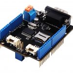
Hacking vehicles becomes easy with CAN BUS and Arduino! CAN-BUS Shield which adopts MCP2515 CAN-BUS controller with SPI interface and MCP2551 CAN transceiver to give you Arduino/Seeeduino CAN-BUS capability. With the help of CAN-BUS Shield, you can use easily interact with your car by using Arduino boards.
CAN-BUS is a common industrial bus because of its long travel distance, medium communication speed, and high reliability. It is commonly found on modern machine tools and as an automotive diagnostic bus.
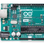
CAN-BUS Shield Work well with Arduino UNO (ATmega328), Arduino Mega (ATmega1280/2560) as well as Arduino Leonardo (ATmega32U4) and LinkIt One, if you want to use it with the others board, please contact us for more details.
| Seeeduino V4.2 | Arduino UNO | Arduino Mega | Arduino Leonardo | |
| CAN-Bus Shield V2 | Compatible | Compatible | Compatible | Compatible |
What is CAN?
- CAN which stands for Controller Area Network is used to allow microcontrollers and devices to communicate with each other within a vehicle without a host computer which allows for control and data acquisition. These devices are also called Electronic Control Units (ECU) and they enable communication between all parts of a vehicle.
- CAN is a serial communication bus designed for industrial and automotive applications. For example, they are found in vehicles, farming equipment, industrial environments, etc
Previously we have made two versions of CAN-BUS Shield, V1.0, and V1.2. They are all awesome shields that widely liked by our users. In order to make it better, several months ago we conducted a survey about CAN-BUS Shield V1.2 and received much valuable advice (Thanks to all the users who replied to us), so we decided to make an update and here it is – CAN-BUS Shield V2.
CAN-BUS Shield Different Versions Comparision
- OBD-II or CAN standard pinout can be selected by switching jumpers on the DB9 interface, the default pinout is OBD-II.
- Added a TF card slot for data storage, and the CS pin can be either set to D4 or D5.
- The INT pin can also be set to D2 or D3 by switching jumpers on the back of the shield.
- We moved the P1 pad from front to the back of the shield to make it easier to cut and solder in case you want to use more than 2 CAN-BUS Shields, it is needed to cut the P1 pad.
- All in one, there are more options for customization.
| Features | V1.2 | V2.0 |
| CAN-BUS Controller | MCP2515 | MCP2515 |
| CAN Transceiver | MCP2551 | MCP2551 |
| Default OBD Pinout | OBD-II Standard | OBD-II Standard |
| CAN Standard Pinout | Not compatible | Compatible (jumper) |
| INT Pin | Not changeable | D2 or D3 (jumper) |
| CS pin for TF card slot | No TF card slot | D4 or D5 (jumper) |
| P1 pad | Front of the shied | Back of the shield |
| Serial Grove | D0/D1 | A0/A1 |
| I2C Grove | A4/A5 | SDA/SCL |
| Grove Orientation | Vertical | Horizontal |
Can-BUS Communication Structure
Consider that the D0/D1 pin is usually used for downloading code, we changed the serial Grove connector to pin A0/A1. The I2C Grove connector is also changed to a more reasonable standard SDA/SCL pins instead of the previous A4/A5. The two Grove connectors are both changed to horizontal rather than vertical to the shield so that it would be more convenient when connecting to other grove modules.
Alternative Choice
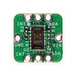
If you want a CAN BUS function for other MCU, please try the Serial CAN-BUS module.
If your project is space limited, here is a Serial CAN-BUS($14.90) module which has the full features of CAN Bus. The Serial CAN-BUS provides your Arduino or other MCU with the capability of communication to CAN Bus, such as hacking your vehicle. This Grove CAN-BUS module is controlled by UART, which means if your MCU has a UART interface, this serial CAN-BUS is available.
If you want to record the GPS log at the same time, this OBD-II CAN Bus GPS Development Kit is recommended.
Tip
Still feel confused about what is CAN BUS and how to use it? Check Introduction to CAN BUS and How to use it with Arduino to get started now!
Tip
We also prepared blog MCP2515 CAN-BUS Arduino Tutorial – Getting started, Interfacing, Applications to help you learn MCP2515 in detail.
Hardware Overview
Technical details
| Dimensions | 74.8mm x53.4mm x27.1mm |
| Weight | G.W 48g |
| Battery | Exclude |
Part List
| CAN-BUS Shield V2 | 1 |
ECCN/HTS
| HSCODE | 8517709000 |
| USHSCODE | 8517700000 |
| UPC | 841454120124 |
CAN-BUS Shield V2 adopts MCP2515 and MCP2551
$27.00
CAN-BUS Shield V2 adopts MCP2515 and MCP2551 for controller and transceiver, it is compatible with Arduino which means it can switch an Arduino board like Arduino Uno to start your CAN-BUS project.
CAN-BUS Shield V2 adopts MCP2515 and MCP2551
$27.00
CAN-BUS Shield V2 adopts MCP2515 and MCP2551 for controller and transceiver, it is compatible with Arduino which means it can switch an Arduino board like Arduino Uno to start your CAN-BUS project.
PRODUCT DETAILS
Features
- Implements CAN V2.0B at up to 1 Mb/s
- Industrial standard 9 pin sub-D connector
- OBD-II and CAN standard pinout selectable.
- Changeable chip select pin
- Changeable CS pin for TF card slot
- Changeable INT pin
- Screw terminal that easily to connect CAN_H and CAN_L
- Arduino Uno pin headers
- Micro SD card holder
- 2 Grove connectors (I2C and UART)
- SPI Interface up to 10 MHz
- Standard (11 bit) and extended (29 bit) data and remote frames
- Two receive buffers with prioritized message storage
Description
Hacking vehicles becomes easy with CAN BUS and Arduino! CAN-BUS Shield which adopts MCP2515 CAN-BUS controller with SPI interface and MCP2551 CAN transceiver to give you Arduino/Seeeduino CAN-BUS capability. With the help of CAN-BUS Shield, you can use easily interact with your car by using Arduino boards.
CAN-BUS is a common industrial bus because of its long travel distance, medium communication speed, and high reliability. It is commonly found on modern machine tools and as an automotive diagnostic bus.
CAN-BUS Shield Work well with Arduino UNO (ATmega328), Arduino Mega (ATmega1280/2560) as well as Arduino Leonardo (ATmega32U4) and LinkIt One, if you want to use it with the others board, please contact us for more details.
| Seeeduino V4.2 | Arduino UNO | Arduino Mega | Arduino Leonardo | |
| CAN-Bus Shield V2 | Compatible | Compatible | Compatible | Compatible |
What is CAN?
- CAN which stands for Controller Area Network is used to allow microcontrollers and devices to communicate with each other within a vehicle without a host computer which allows for control and data acquisition. These devices are also called Electronic Control Units (ECU) and they enable communication between all parts of a vehicle.
- CAN is a serial communication bus designed for industrial and automotive applications. For example, they are found in vehicles, farming equipment, industrial environments, etc
Previously we have made two versions of CAN-BUS Shield, V1.0, and V1.2. They are all awesome shields that widely liked by our users. In order to make it better, several months ago we conducted a survey about CAN-BUS Shield V1.2 and received much valuable advice (Thanks to all the users who replied to us), so we decided to make an update and here it is – CAN-BUS Shield V2.
CAN-BUS Shield Different Versions Comparision
- OBD-II or CAN standard pinout can be selected by switching jumpers on the DB9 interface, the default pinout is OBD-II.
- Added a TF card slot for data storage, and the CS pin can be either set to D4 or D5.
- The INT pin can also be set to D2 or D3 by switching jumpers on the back of the shield.
- We moved the P1 pad from front to the back of the shield to make it easier to cut and solder in case you want to use more than 2 CAN-BUS Shields, it is needed to cut the P1 pad.
- All in one, there are more options for customization.
| Features | V1.2 | V2.0 |
| CAN-BUS Controller | MCP2515 | MCP2515 |
| CAN Transceiver | MCP2551 | MCP2551 |
| Default OBD Pinout | OBD-II Standard | OBD-II Standard |
| CAN Standard Pinout | Not compatible | Compatible (jumper) |
| INT Pin | Not changeable | D2 or D3 (jumper) |
| CS pin for TF card slot | No TF card slot | D4 or D5 (jumper) |
| P1 pad | Front of the shied | Back of the shield |
| Serial Grove | D0/D1 | A0/A1 |
| I2C Grove | A4/A5 | SDA/SCL |
| Grove Orientation | Vertical | Horizontal |
Can-BUS Communication Structure
Consider that the D0/D1 pin is usually used for downloading code, we changed the serial Grove connector to pin A0/A1. The I2C Grove connector is also changed to a more reasonable standard SDA/SCL pins instead of the previous A4/A5. The two Grove connectors are both changed to horizontal rather than vertical to the shield so that it would be more convenient when connecting to other grove modules.
Alternative Choice
If you want a CAN BUS function for other MCU, please try the Serial CAN-BUS module.
If your project is space limited, here is a Serial CAN-BUS($14.90) module which has the full features of CAN Bus. The Serial CAN-BUS provides your Arduino or other MCU with the capability of communication to CAN Bus, such as hacking your vehicle. This Grove CAN-BUS module is controlled by UART, which means if your MCU has a UART interface, this serial CAN-BUS is available.
If you want to record the GPS log at the same time, this OBD-II CAN Bus GPS Development Kit is recommended.
Tip
Still feel confused about what is CAN BUS and how to use it? Check Introduction to CAN BUS and How to use it with Arduino to get started now!
Tip
We also prepared blog MCP2515 CAN-BUS Arduino Tutorial – Getting started, Interfacing, Applications to help you learn MCP2515 in detail.
Hardware Overview
Technical details
| Dimensions | 74.8mm x53.4mm x27.1mm |
| Weight | G.W 48g |
| Battery | Exclude |
Part List
| CAN-BUS Shield V2 | 1 |
ECCN/HTS
| HSCODE | 8517709000 |
| USHSCODE | 8517700000 |
| UPC | 841454120124 |
